University of Alabama
Flight Dynamics Laboratory
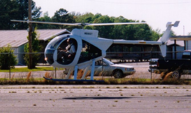
Mini500 Helicopter
Operations Log
25 Mar 2000 Engine started for the first time and broken in bY Mr. Joe Green
Hobbs time and Mr. Gary Nash. 5 gal of fuel mixed with oil were used, and
0.1-0.6 then 5 gals without oil poured in.
04 Apr 2000 Aircraft inspected by DAR Mr. John Burgin and issued certificate
of airworthiness and operating limitations.
06 Apr 2000 7.5 lb of lead shot added as ballast to the front of each skid.
Engine time Ballast contained in burlap "socks," poured in place. When full,
1.6-2.0 sock expands and friction maintains it in place.
Cyclic adjustment: rear control rod #165 shortened to move cyclic
travel range aft and prevent cyclic handle from making contact
with instrument panel.
Aircraft was fueled with 5 gal of fuel mixed with oil. Level of
oil in tank was marked with green tape.
Engine was started and hover trials made with A. Katz at the
controls.
 It was verified that oil level in oil tank dropped.
Discrepancies:
Engine tachometer off. EIS indicates correct engine RPM. Input
disconnected from EIS, but problem persisted.
Coolant temperature reading reduced when EIS is on. This input
disconnected from EIS.
No EGT indication. Wiring fault corrected.
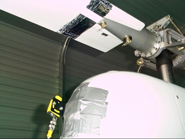
Started the installation of the balancer. Photo tach attached to
front of turtle deck with duct tape. 2" of relective tape
attached to bottom of blade A. Could not attach accelerometer
because the self tapping screw used on the bottom of the windshield
trim was oversize.
Post-flight inspection: Belt moved fwd and now is at edge of
transmission wheel.
07 Apr 2000 Attached accelerometer to aircraft nose with 3/16" machine screw
secured by nut & 2 washers.
11 Apr 2000 Cyclic can still be forced into contact with instrument panel by
Engine time bending. Rear control rod #165 shortened further to move cyclic
2.0-2.4 travel range aft and prevent contact with instrument panel.
Belt tracking adjusted to leave 1/8" margin at front of
transmission wheel. Belt tension rechecked.
A piece of duct tape was attached to blade B to balance the
reflecting tape on blade A.
Engine was started and the following procedures carried out on
the ground and in hover:
Adjusted engine tach to agree with rotor tach approximately.
Exact agreement not attained.
Tried balancer on ground. RPM readings too high (~13K). Removed
duct tape from blade B. Got correct RPM (546) and sample
vibration reading on ground. In hover, RPM not correct. Did not
get hover vib readings because collective tends to rise, if left
alone, and access to balancer button difficult.
Flight operations aborted when drive belt became frayed. This
resulted from the nut #463 becoming loose and falling off the
drive idler arm screw #205. The nut was recovered.
Partial disassembly was begun to allow replacement of the drive
belt. Rear control rod #165, clutch bearing housing #209 and
tension barrels #133 (2) removed. The tail rotor drive was
separated from the coupler plate. The tail, tail rotor
transmission and tail rotor were also removed. However, this
still did not allow the drive belt to be taken out.
It was verified that oil level in oil tank dropped.
Discrepancies:
Engine tachometer off. EIS indicates correct engine RPM. Input
disconnected from EIS, but problem persisted.
Coolant temperature reading reduced when EIS is on. This input
disconnected from EIS.
No EGT indication. Wiring fault corrected.
Started the installation of the balancer. Photo tach attached to
front of turtle deck with duct tape. 2" of relective tape
attached to bottom of blade A. Could not attach accelerometer
because the self tapping screw used on the bottom of the windshield
trim was oversize.
Post-flight inspection: Belt moved fwd and now is at edge of
transmission wheel.
07 Apr 2000 Attached accelerometer to aircraft nose with 3/16" machine screw
secured by nut & 2 washers.
11 Apr 2000 Cyclic can still be forced into contact with instrument panel by
Engine time bending. Rear control rod #165 shortened further to move cyclic
2.0-2.4 travel range aft and prevent contact with instrument panel.
Belt tracking adjusted to leave 1/8" margin at front of
transmission wheel. Belt tension rechecked.
A piece of duct tape was attached to blade B to balance the
reflecting tape on blade A.
Engine was started and the following procedures carried out on
the ground and in hover:
Adjusted engine tach to agree with rotor tach approximately.
Exact agreement not attained.
Tried balancer on ground. RPM readings too high (~13K). Removed
duct tape from blade B. Got correct RPM (546) and sample
vibration reading on ground. In hover, RPM not correct. Did not
get hover vib readings because collective tends to rise, if left
alone, and access to balancer button difficult.
Flight operations aborted when drive belt became frayed. This
resulted from the nut #463 becoming loose and falling off the
drive idler arm screw #205. The nut was recovered.
Partial disassembly was begun to allow replacement of the drive
belt. Rear control rod #165, clutch bearing housing #209 and
tension barrels #133 (2) removed. The tail rotor drive was
separated from the coupler plate. The tail, tail rotor
transmission and tail rotor were also removed. However, this
still did not allow the drive belt to be taken out.
 13 Apr 2000 Disconnected lower attach points of rear mast support arms.
2.4 Removed the two eyebolts that attach the tail boom to the frame.
Also disconnected upper left tail boom support from frame at
firewall. With this done, the worn drive belt was removed. The
tail parts previously removed unnecessarily (tail transmission
and rotor and tail surfaces, were reattached to the tail boom.
The drive belt was identified as B1200AM50 (1200mm circumference,
50 mm wide.) A replacement was ordered from Power & Rubber Supply
Co. of Tuscaloosa.
Oil drained from tail rotor transmission and not refilled for
lack of a measuring cup.
13 Apr 2000 Disconnected lower attach points of rear mast support arms.
2.4 Removed the two eyebolts that attach the tail boom to the frame.
Also disconnected upper left tail boom support from frame at
firewall. With this done, the worn drive belt was removed. The
tail parts previously removed unnecessarily (tail transmission
and rotor and tail surfaces, were reattached to the tail boom.
The drive belt was identified as B1200AM50 (1200mm circumference,
50 mm wide.) A replacement was ordered from Power & Rubber Supply
Co. of Tuscaloosa.
Oil drained from tail rotor transmission and not refilled for
lack of a measuring cup.
 18 Apr 2000 New drive belt installed. Tail boom reconnected (bolts and
Engine time eyelets secured with blue locktite). Rear mast support arms
2.4-3.0 reconnected. Clutch support plates reinstalled and safety wired.
Tension barrels reinstalled. Rear control rod reinstalled. Belt
tension adjusted and checked. Belt idler secured with a nylock
nut. Tail transmission filled with 3+ ounces of transmission oil.
5 gals of fuel without oil added to tank.
The engine was started and the aircraft was hovered includeing
hover taxi and hover turns. A second flight used to attempt a
measurement of vibration level. Levels ranging from 0.35ips to
1.5 ips were indicated depending on wind condition and flight
condition. However, no tach reading or wrong tach reading most of
the time. Balancer reads photocell correctly during static
checks.
22 Apr 2000 Trouble shooting session:
Engine time * Determined that crack between air filter and holder does not
3.0-3.2 admit air into carburetors.
* Determined that Hobbs meter not powered thru either master or
avionics master switch. Rather, it is powered directly from the
rectifier. This way, it records engine time.
* Corrected error in wiring of EGT wires. EGT gages now work.
* Lengthened tension barrels, after which spinning rotor by hand
moves belt to 1/8" aft of edge of transmission gear. Vibration
level in flight low. After shut down, belt at edge again.
Spinning rotor by hand brings it back to 1/8" behind edge.
* Adjusted engine tach to agree with rotor tach at 100%.
* Reinstalled photocell unit of balancer with masking tape
painted black on both blades and the reflective tape on top of
the masking tape. Now balancer reads correctly both on the
ground and in hover. Too windy to collect balance data.
28 Apr 2000 Hover demo for AEM Advisory board. Windy conditions. Vibration
Engine time level high.
3.2-3.3
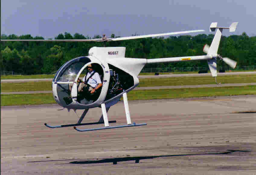
11 Jun 2000 Photo session with J. Lipkin. Hover taxi & turns. Vibration level
3.3-3.5 low.
14 Jun 2000 Hover maneuvers. Could not take vibration readings because
3.5-3.8 balancer dead. Vibration level low.
16 Jun 2000 Hover maneuvers. Flight time 0.8. Rest of time spent trying to
3.8-5.0 make balancer work. RPM reads too high most of the time (e.g.,
~3000 instead of 118). Reblackened masking tape. blackened
additional area on blades. replaced reflective tape, replaced
balancer battery, repositioned photocel -- no luck. Cloudy day
with occasional sprinkle, wind. Vibration average measurements
taken (azimuth meaningles):
First flight Second flight
0.19 172 0.06 336
0.48 285 0.21 68
0.13 341 0.16 162
0.29 306 0.27 331
0.35 279
23 Jun 2000 Hover maneuvers. Balancer still does not work. Sky was fair with
5.0-5.3 some high clouds. Large drop in engine RPM indication on right
mag (has been this way). Rotor RPM unaffected. Exhaust gas temp
remains normal for both cylinders. Hovered on right mag -- no
effect on power. Throttle friction adjusted (in engine compartment).
Throttle still tends to roll off when left alone, but remains
stable with hand resting on it.
26 Jun 2000 Balancer with photocell unit & cable shipped to manufacturer for
5.3 inspection.
28 Jun 2000 Replaced oil in main & tail transmissions. Topped off coolant.
5.3
30 Jun 2000 Balancer returned with replacement photocell unit & cable.
18 Apr 2000 New drive belt installed. Tail boom reconnected (bolts and
Engine time eyelets secured with blue locktite). Rear mast support arms
2.4-3.0 reconnected. Clutch support plates reinstalled and safety wired.
Tension barrels reinstalled. Rear control rod reinstalled. Belt
tension adjusted and checked. Belt idler secured with a nylock
nut. Tail transmission filled with 3+ ounces of transmission oil.
5 gals of fuel without oil added to tank.
The engine was started and the aircraft was hovered includeing
hover taxi and hover turns. A second flight used to attempt a
measurement of vibration level. Levels ranging from 0.35ips to
1.5 ips were indicated depending on wind condition and flight
condition. However, no tach reading or wrong tach reading most of
the time. Balancer reads photocell correctly during static
checks.
22 Apr 2000 Trouble shooting session:
Engine time * Determined that crack between air filter and holder does not
3.0-3.2 admit air into carburetors.
* Determined that Hobbs meter not powered thru either master or
avionics master switch. Rather, it is powered directly from the
rectifier. This way, it records engine time.
* Corrected error in wiring of EGT wires. EGT gages now work.
* Lengthened tension barrels, after which spinning rotor by hand
moves belt to 1/8" aft of edge of transmission gear. Vibration
level in flight low. After shut down, belt at edge again.
Spinning rotor by hand brings it back to 1/8" behind edge.
* Adjusted engine tach to agree with rotor tach at 100%.
* Reinstalled photocell unit of balancer with masking tape
painted black on both blades and the reflective tape on top of
the masking tape. Now balancer reads correctly both on the
ground and in hover. Too windy to collect balance data.
28 Apr 2000 Hover demo for AEM Advisory board. Windy conditions. Vibration
Engine time level high.
3.2-3.3
11 Jun 2000 Photo session with J. Lipkin. Hover taxi & turns. Vibration level
3.3-3.5 low.
14 Jun 2000 Hover maneuvers. Could not take vibration readings because
3.5-3.8 balancer dead. Vibration level low.
16 Jun 2000 Hover maneuvers. Flight time 0.8. Rest of time spent trying to
3.8-5.0 make balancer work. RPM reads too high most of the time (e.g.,
~3000 instead of 118). Reblackened masking tape. blackened
additional area on blades. replaced reflective tape, replaced
balancer battery, repositioned photocel -- no luck. Cloudy day
with occasional sprinkle, wind. Vibration average measurements
taken (azimuth meaningles):
First flight Second flight
0.19 172 0.06 336
0.48 285 0.21 68
0.13 341 0.16 162
0.29 306 0.27 331
0.35 279
23 Jun 2000 Hover maneuvers. Balancer still does not work. Sky was fair with
5.0-5.3 some high clouds. Large drop in engine RPM indication on right
mag (has been this way). Rotor RPM unaffected. Exhaust gas temp
remains normal for both cylinders. Hovered on right mag -- no
effect on power. Throttle friction adjusted (in engine compartment).
Throttle still tends to roll off when left alone, but remains
stable with hand resting on it.
26 Jun 2000 Balancer with photocell unit & cable shipped to manufacturer for
5.3 inspection.
28 Jun 2000 Replaced oil in main & tail transmissions. Topped off coolant.
5.3
30 Jun 2000 Balancer returned with replacement photocell unit & cable.
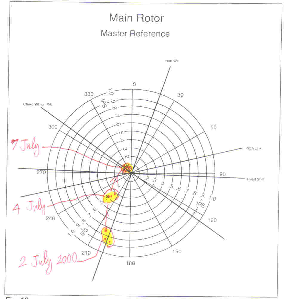
 02 Jul 2000 New photocell unit installed on helicopter. Balancer now works.
5.3-5.7 The following averaged readings obtained:
In hover at altitude AGL Vib level Azimuth
(ft) (ips) (deg)
-------------------------------
0 0.80 280
............................
2 0.86 202
5 0.75 204
10 0.87 196
Azimuth is close to the hub weight shift line. Sensitivity quoted
in manual as 0.0279 ips/g. Need approx. 30g on blade B.
03 Jul 2000 Replaced washers at both ends of outboard bolt (#407) with
5.7 oversize washers. Replacement washers weighs 16g, original weighs
2g. Added weight 28g.
04 Jul 2000 Vibration averaged readings taken under windless conditions:
5.7-6.1 In hover at altitude AGL Vib level Azimuth Sensitivity
(ft) (ips) (deg) (ips/g)
---------------------------------------------
0 0.45 296
0 0.16 254
.......................................
2 0.39 224 0.0168
5 0.36 220 0.0139
10 0.31 215 0.0200
----------
Average 0.0169
Sensitivity less than published. Direction of move ~180 deg vs
The published 200. More mass needed on blade B.
07 Jul 2000 Replaced bolt #407 (40g) on blade B by a longer AN6-25 (45g).
6.1-7.1 Installed with one regular washer and one oversize washer (30g)
on top and two on the bottom, altogether ~35g increase.
Vibration averaged readings taken under windless conditions:
In hover at altitude AGL Vib level Azimuth Sensitivity
(ft) (ips) (deg) (ips/g)
---------------------------------------------
0 0.24 358
..........................
2 0.12 315
5 0.11 299
10 0.09 329
Added 2 oversize washers to bolt #369 at pitch link on blade B.
Vibration averaged readings taken under near windless conditions:
In hover at altitude AGL Vib level Azimuth Sensitivity
(ft) (ips) (deg) (ips/g)
---------------------------------------------
0 0.38 280
..........................
2 0.06 309
5 0.07 283
10 0.06 330
With all readings below 0.1ips, the main rotor is balanced for
1 per rev vibrations.
02 Jul 2000 New photocell unit installed on helicopter. Balancer now works.
5.3-5.7 The following averaged readings obtained:
In hover at altitude AGL Vib level Azimuth
(ft) (ips) (deg)
-------------------------------
0 0.80 280
............................
2 0.86 202
5 0.75 204
10 0.87 196
Azimuth is close to the hub weight shift line. Sensitivity quoted
in manual as 0.0279 ips/g. Need approx. 30g on blade B.
03 Jul 2000 Replaced washers at both ends of outboard bolt (#407) with
5.7 oversize washers. Replacement washers weighs 16g, original weighs
2g. Added weight 28g.
04 Jul 2000 Vibration averaged readings taken under windless conditions:
5.7-6.1 In hover at altitude AGL Vib level Azimuth Sensitivity
(ft) (ips) (deg) (ips/g)
---------------------------------------------
0 0.45 296
0 0.16 254
.......................................
2 0.39 224 0.0168
5 0.36 220 0.0139
10 0.31 215 0.0200
----------
Average 0.0169
Sensitivity less than published. Direction of move ~180 deg vs
The published 200. More mass needed on blade B.
07 Jul 2000 Replaced bolt #407 (40g) on blade B by a longer AN6-25 (45g).
6.1-7.1 Installed with one regular washer and one oversize washer (30g)
on top and two on the bottom, altogether ~35g increase.
Vibration averaged readings taken under windless conditions:
In hover at altitude AGL Vib level Azimuth Sensitivity
(ft) (ips) (deg) (ips/g)
---------------------------------------------
0 0.24 358
..........................
2 0.12 315
5 0.11 299
10 0.09 329
Added 2 oversize washers to bolt #369 at pitch link on blade B.
Vibration averaged readings taken under near windless conditions:
In hover at altitude AGL Vib level Azimuth Sensitivity
(ft) (ips) (deg) (ips/g)
---------------------------------------------
0 0.38 280
..........................
2 0.06 309
5 0.07 283
10 0.06 330
With all readings below 0.1ips, the main rotor is balanced for
1 per rev vibrations.
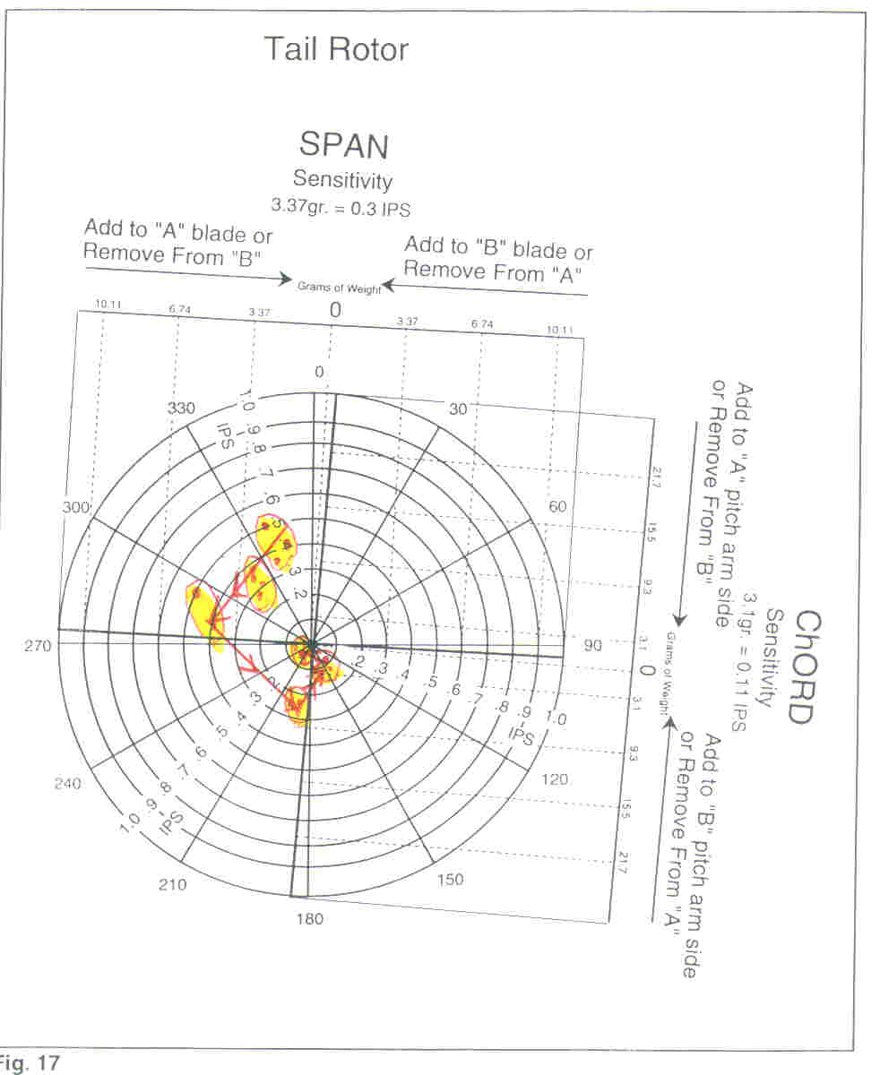
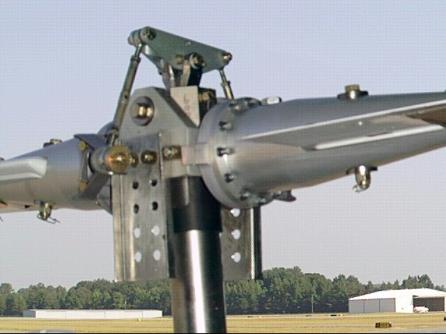
 10 Jul 2000 Moved balancer to tail rotor and installed on left front bolt of
7.1-7.8 tail rotor transmission using the bracket supplied with the new
photocell. A square of reflective tape was placed on tail rotor
hub plate (#56) on the blade A side and a similar square of duct
tape at blade B. Vibration measurements were taken on the ground
with rotor RPM at top of green, flat pitch, cyclic and pedals
centered.
Vibration averaged readings taken under near windless conditions:
Vibration level (ips) azimuth (deg)
----------------------------------------
0.50 339
0.35 338
0.40 345
Removed from B cordwise large washer and replaced with ordinary
washer
Vibration level (ips) azimuth (deg)
----------------------------------------
0.38 326
0.36 322
0.29 314
0.32 322
Remove the whole bolt holding chordwise weight on B side
Vibration level (ips) azimuth (deg)
----------------------------------------
0.50 296
0.39 279
Conclusion: with this installation, move is at 45 deg to that
indicated in manual. At this point put spanwise weight on blade A
by replacing washer with an oversize washer
Vibration level (ips) azimuth (deg)
----------------------------------------
0.23 190
0.28 190
0.24 198
This move also shifted 45 deg. Now backed up on chordwise weight
by returning bolt and spacer and installing with lightweight
washer.
Vibration level (ips) azimuth (deg)
----------------------------------------
0.09 143
0.08 154
0.13 153
0.10 159
0.12 149
0.04 163
Now backed a little on spanwise weight by adding second regular
washer on blade B.
Vibration level (ips) azimuth (deg)
----------------------------------------
0.06 217
0.06 263
0.03 266
At this point tail rotor is balanced. Returned balancer to main
rotor.
10 Jul 2000 Moved balancer to tail rotor and installed on left front bolt of
7.1-7.8 tail rotor transmission using the bracket supplied with the new
photocell. A square of reflective tape was placed on tail rotor
hub plate (#56) on the blade A side and a similar square of duct
tape at blade B. Vibration measurements were taken on the ground
with rotor RPM at top of green, flat pitch, cyclic and pedals
centered.
Vibration averaged readings taken under near windless conditions:
Vibration level (ips) azimuth (deg)
----------------------------------------
0.50 339
0.35 338
0.40 345
Removed from B cordwise large washer and replaced with ordinary
washer
Vibration level (ips) azimuth (deg)
----------------------------------------
0.38 326
0.36 322
0.29 314
0.32 322
Remove the whole bolt holding chordwise weight on B side
Vibration level (ips) azimuth (deg)
----------------------------------------
0.50 296
0.39 279
Conclusion: with this installation, move is at 45 deg to that
indicated in manual. At this point put spanwise weight on blade A
by replacing washer with an oversize washer
Vibration level (ips) azimuth (deg)
----------------------------------------
0.23 190
0.28 190
0.24 198
This move also shifted 45 deg. Now backed up on chordwise weight
by returning bolt and spacer and installing with lightweight
washer.
Vibration level (ips) azimuth (deg)
----------------------------------------
0.09 143
0.08 154
0.13 153
0.10 159
0.12 149
0.04 163
Now backed a little on spanwise weight by adding second regular
washer on blade B.
Vibration level (ips) azimuth (deg)
----------------------------------------
0.06 217
0.06 263
0.03 266
At this point tail rotor is balanced. Returned balancer to main
rotor.
 11 Jul 2000 Verified balancer operation. Then, with reflective strips on both
7.8-8.6 blades took 2/rev (1/blade) readings. Avg in hover:
Vibration level (ips) azimuth (deg)
----------------------------------------
0.53 100
0.79 122
0.84 123
0.61 111
Vib level increases in fwd motion to 1.2-1.5. In slow rearward
motion or when stopping it drops to 0.25-0.35, picks up again as
rearward motion accelerates.
13 Jul 2000 Approximate Azimuth of 2/rev vs direction of translation in hover:
8.6-9.2
Fwd Left Aft Right
Reading 140 40 300 200
Coning* 180 90 360 270
Residual+ 270 180 90 0
Differences
from coning -40 -50 -60 -70
from residual -130 -140 -150 -160
Results appear consistent with insufficient undersling.
11 Jul 2000 Verified balancer operation. Then, with reflective strips on both
7.8-8.6 blades took 2/rev (1/blade) readings. Avg in hover:
Vibration level (ips) azimuth (deg)
----------------------------------------
0.53 100
0.79 122
0.84 123
0.61 111
Vib level increases in fwd motion to 1.2-1.5. In slow rearward
motion or when stopping it drops to 0.25-0.35, picks up again as
rearward motion accelerates.
13 Jul 2000 Approximate Azimuth of 2/rev vs direction of translation in hover:
8.6-9.2
Fwd Left Aft Right
Reading 140 40 300 200
Coning* 180 90 360 270
Residual+ 270 180 90 0
Differences
from coning -40 -50 -60 -70
from residual -130 -140 -150 -160
Results appear consistent with insufficient undersling.
 20 Jul 2000 Mounted teeter balance brackets on hub plates (#12) by bolts #398
9.2-9.9 with washers removed. Each teeter plate weighs 165g.
On the ground (collective down) vibration level was 0.82 ips, and
the azimuth as a function of cyclic stick deflection was
Cyclic input Fwd Left Aft Right
Azimuth 180 45 340 260
Coning* 180 90 360 270
Residual+ 270 180 90 0
Differences
from coning 0 -45 -20 -10 0.91
from residual -90 -135 -110 -100 -0.31
In stationary hover in a light wind took average 1/blade
vibration measurements with different headings:
Wind from: Fwd Left Aft Right Average
Vib level (ips) 0.64 0.66 0.13 0.93 Cosine
Azimuth 71 64 252 185
Coning* 180 90 360 270
Residual+ 270 180 90 0
Differences
from coning -109 -26 -108 -85 = 0.088
from residual 161 -116 162 -175 = -0.83
Average from coning
*"Coning" is for inertial effect due to insufficient undersling.
+"Residual" is due to residual bending.
Interpretation: resonant mode at 1.69Omega (vs 1.25Omega for
original Mini500, 1.49Omega for one with Revolution mast support.)
For rotor tilted forward, azimuth readings associated with coning
and residual (2 per rev) are:
drive response
Coning 180 31
Residual 270 121
Measured response is at ~70, being combination of both. Need to
lower rotor CG further to eliminate coning effect.
28 Jul 2000 Took measurements in hover in no wind or light & variable. The
9.9-11.1 purpose was to reestablish previous result. However, results
scattered:
Hvering at 2 ft (averaged readings):
level (ips) 1.02 0.55 0.85 0.66 0.31 0.53 0.53 0.83
azimuth 119 107 135 143 120 166 140 97
Hvering at 10 ft (averaged readings):
level (ips) 0.52 0.62 0.66
azimuth 91 72 32
Added a bolt with 14 washers & locknut at one lowest hole on the
teeter bracket on each side. Added mass 55g.
20 Jul 2000 Mounted teeter balance brackets on hub plates (#12) by bolts #398
9.2-9.9 with washers removed. Each teeter plate weighs 165g.
On the ground (collective down) vibration level was 0.82 ips, and
the azimuth as a function of cyclic stick deflection was
Cyclic input Fwd Left Aft Right
Azimuth 180 45 340 260
Coning* 180 90 360 270
Residual+ 270 180 90 0
Differences
from coning 0 -45 -20 -10 0.91
from residual -90 -135 -110 -100 -0.31
In stationary hover in a light wind took average 1/blade
vibration measurements with different headings:
Wind from: Fwd Left Aft Right Average
Vib level (ips) 0.64 0.66 0.13 0.93 Cosine
Azimuth 71 64 252 185
Coning* 180 90 360 270
Residual+ 270 180 90 0
Differences
from coning -109 -26 -108 -85 = 0.088
from residual 161 -116 162 -175 = -0.83
Average from coning
*"Coning" is for inertial effect due to insufficient undersling.
+"Residual" is due to residual bending.
Interpretation: resonant mode at 1.69Omega (vs 1.25Omega for
original Mini500, 1.49Omega for one with Revolution mast support.)
For rotor tilted forward, azimuth readings associated with coning
and residual (2 per rev) are:
drive response
Coning 180 31
Residual 270 121
Measured response is at ~70, being combination of both. Need to
lower rotor CG further to eliminate coning effect.
28 Jul 2000 Took measurements in hover in no wind or light & variable. The
9.9-11.1 purpose was to reestablish previous result. However, results
scattered:
Hvering at 2 ft (averaged readings):
level (ips) 1.02 0.55 0.85 0.66 0.31 0.53 0.53 0.83
azimuth 119 107 135 143 120 166 140 97
Hvering at 10 ft (averaged readings):
level (ips) 0.52 0.62 0.66
azimuth 91 72 32
Added a bolt with 14 washers & locknut at one lowest hole on the
teeter bracket on each side. Added mass 55g.
 Hvering at 10 ft (averaged readings):
level (ips) 0.35 0.77 1.07 0.80 0.60 0.53
azimuth 125 149 145 124 132 129
Hvering at 10 ft (averaged readings):
level (ips) 0.35 0.77 1.07 0.80 0.60 0.53
azimuth 125 149 145 124 132 129
 Subjectively things appear smoother with added weight. Still very
noticeable increase of vibration in fwd motion. Readings well
above 1.0, subjective feeling of lateral vibration.
30 Jul 2000 Removed turtle deck and inspected underneath. Found drive belt
11.1 slightly over edge of transmission gear. Lengthened each of the
clutch tension barrels (#133) by one turn. Found two cracks
starting in lower rear of turtle deck.
31 Jul 2000 Adjusted belt tension (adjusment amounted to one turn of lock
11.1-11.9 nut). Stop drilled cracks in turtle deck.
Took two per rev vibration readings in stationary hover in 4 knot
wind: facing wind:
level (ips) 1.45 1.40 1.98 1.39
------------------------------------------
azimuth (deg) 114 103 81 111
with back to wind
level (ips) 0.19 0.83 0.56
-----------------------------------
azimuth (deg) 170 183 137
Subjectively things appear smoother with added weight. Still very
noticeable increase of vibration in fwd motion. Readings well
above 1.0, subjective feeling of lateral vibration.
30 Jul 2000 Removed turtle deck and inspected underneath. Found drive belt
11.1 slightly over edge of transmission gear. Lengthened each of the
clutch tension barrels (#133) by one turn. Found two cracks
starting in lower rear of turtle deck.
31 Jul 2000 Adjusted belt tension (adjusment amounted to one turn of lock
11.1-11.9 nut). Stop drilled cracks in turtle deck.
Took two per rev vibration readings in stationary hover in 4 knot
wind: facing wind:
level (ips) 1.45 1.40 1.98 1.39
------------------------------------------
azimuth (deg) 114 103 81 111
with back to wind
level (ips) 0.19 0.83 0.56
-----------------------------------
azimuth (deg) 170 183 137
 Went about 3000 ft on taxiway 04 and back. Reached indicated
airspeed of 45 knots. Saw 2/rev vib levels up to 3.25. Highest
levels around ETL, then back down to ~1.7.
Drive belt moved slightly over front of transmission gear.
05 Aug 2000 Removed turtle deck and inspected underneath. Shortened each of
11.9 the clutch tension barrels (#133) until top of clutch support
plates #206 & #207 was parallel to transmission and adjusted belt
tension. In the process, belt moved well aft of front edge of
transmission gear.
09 Aug 2000 In no wind condition tried effect of ballast at the nose on 2/rev
11.9-12.2 levels. Ballast was initially at firewall, then moved to nose.
Average readings:
Ballast level Azimuth
(kg) (ips) (deg)
0 0.67 93
7.660 0.46 77
4.735 0.46 67
Drive belt moved forward and was damaged. Heard 3 pops, and put
helicopter down. Smelled oil. There was oil on and near the
clutch.
10 Aug 2000 Oil came from transmission through bearing of the drive gear.
12.2 Changed the transmission oil. The transmission was nearly full.
Left a cup in place to catch any flow, but there seems not to be
any.
12 Aug 2000 Fuel leak developed at bottom of sight gage line. Fuel created
12.2 puddle on floor of cabin. Fixed leak by moving and retightening
clamp. Drilled a drain hole at bottom of cabin. Collected ~1.5
gal of fuel.
Removed damaged drive belt using following procedure:
1. Reduced belt tension by moving idler out of the way as far as
it can go.
2. Disconnected drive plate (#119) from both transmission and
tail rotor drive shaft.
3. Disconnected bottom ends of rear mast support arms from
eyebolts.
4. Provided external support for tail boom.
5. Removed eybolts (they hold the tail boom attach plate to
airframe.)
6. Undid bolt that holds left upper tail boom support to top of
airframe near firewall.
7. Now tail boom could be maneuvered to provide enough space to
remove drive plate (#119). The drive belt was also slipped
through the same space and now encircled only the lower pulley
near the clutch.
8. Removed the four bolts (2 on each side) that hold clutch
bearing housing (#209) to the clutch support plates (#206,207).
9. Loosened the 4 bolts that attach the clutch support plates
(#206,207) to the engine.
10. This provided enough play so that the clutch bearing housing
(#209) could be turned 90 degrees, creating the necessary
opening to remove the drive belt.
18 Aug 2000 Installed new drive belt:
12.2
1. Threaded new belt in place on pulleys.
2. Returned drive plate #119 into place and connected to tail
rotor side.
3. Reconnected left upper tail boom support to frame (blue lt).
4. Reconnected tail boom attach plate to frame using eyebolts
(blue lt).
5. Reconnected lower end of rear mast support arms to eyebolts.
6. Reinserted 4 bolts that hold clutch support plates (#206.207)
to clutch bearing housing (#2309). Tightened these bolts and
the four bolts thet hold clutch support plates (#206.207) to
the engine.
7. Reconnected drive plate (#119) to transmission side.
21 Aug 2000 Safety wired bolts that hold clutch bearing housing (#2309).
12.2 Safety wired main transmission drain plug & tail transmission
fill plug.
Checked that clutch bearing housing (#2309) is vertically
parallel to mast. This required no load in clutch tension barrels
#133. Could not check directly that power pulley is parallel to
transmission pulley for lack of a small enough level. Idler
slopes slightly down toward front.
25 Aug 2000 Aligned Idler to be parallel to transmission pulley as measured
12.2 by level on each. This was accomplished by reworking holes where
idler support connects to frame and by deforming idler support
arm with a metal bar. Belt tension set and alignments rechecked
and readjusted with tension on.
28 Aug 2000 Monitored belt track and transmission oil leak on the ground and
12.2-12.6 in hover with help of T. Waits. Belt stable behind edge of
pulley. Oil leaks from rear end of transmission. Drop collects on
rear underside of transmission and eventually drops onto clutch.
Flow increases as transmission heats up.
Went about 3000 ft on taxiway 04 and back. Reached indicated
airspeed of 45 knots. Saw 2/rev vib levels up to 3.25. Highest
levels around ETL, then back down to ~1.7.
Drive belt moved slightly over front of transmission gear.
05 Aug 2000 Removed turtle deck and inspected underneath. Shortened each of
11.9 the clutch tension barrels (#133) until top of clutch support
plates #206 & #207 was parallel to transmission and adjusted belt
tension. In the process, belt moved well aft of front edge of
transmission gear.
09 Aug 2000 In no wind condition tried effect of ballast at the nose on 2/rev
11.9-12.2 levels. Ballast was initially at firewall, then moved to nose.
Average readings:
Ballast level Azimuth
(kg) (ips) (deg)
0 0.67 93
7.660 0.46 77
4.735 0.46 67
Drive belt moved forward and was damaged. Heard 3 pops, and put
helicopter down. Smelled oil. There was oil on and near the
clutch.
10 Aug 2000 Oil came from transmission through bearing of the drive gear.
12.2 Changed the transmission oil. The transmission was nearly full.
Left a cup in place to catch any flow, but there seems not to be
any.
12 Aug 2000 Fuel leak developed at bottom of sight gage line. Fuel created
12.2 puddle on floor of cabin. Fixed leak by moving and retightening
clamp. Drilled a drain hole at bottom of cabin. Collected ~1.5
gal of fuel.
Removed damaged drive belt using following procedure:
1. Reduced belt tension by moving idler out of the way as far as
it can go.
2. Disconnected drive plate (#119) from both transmission and
tail rotor drive shaft.
3. Disconnected bottom ends of rear mast support arms from
eyebolts.
4. Provided external support for tail boom.
5. Removed eybolts (they hold the tail boom attach plate to
airframe.)
6. Undid bolt that holds left upper tail boom support to top of
airframe near firewall.
7. Now tail boom could be maneuvered to provide enough space to
remove drive plate (#119). The drive belt was also slipped
through the same space and now encircled only the lower pulley
near the clutch.
8. Removed the four bolts (2 on each side) that hold clutch
bearing housing (#209) to the clutch support plates (#206,207).
9. Loosened the 4 bolts that attach the clutch support plates
(#206,207) to the engine.
10. This provided enough play so that the clutch bearing housing
(#209) could be turned 90 degrees, creating the necessary
opening to remove the drive belt.
18 Aug 2000 Installed new drive belt:
12.2
1. Threaded new belt in place on pulleys.
2. Returned drive plate #119 into place and connected to tail
rotor side.
3. Reconnected left upper tail boom support to frame (blue lt).
4. Reconnected tail boom attach plate to frame using eyebolts
(blue lt).
5. Reconnected lower end of rear mast support arms to eyebolts.
6. Reinserted 4 bolts that hold clutch support plates (#206.207)
to clutch bearing housing (#2309). Tightened these bolts and
the four bolts thet hold clutch support plates (#206.207) to
the engine.
7. Reconnected drive plate (#119) to transmission side.
21 Aug 2000 Safety wired bolts that hold clutch bearing housing (#2309).
12.2 Safety wired main transmission drain plug & tail transmission
fill plug.
Checked that clutch bearing housing (#2309) is vertically
parallel to mast. This required no load in clutch tension barrels
#133. Could not check directly that power pulley is parallel to
transmission pulley for lack of a small enough level. Idler
slopes slightly down toward front.
25 Aug 2000 Aligned Idler to be parallel to transmission pulley as measured
12.2 by level on each. This was accomplished by reworking holes where
idler support connects to frame and by deforming idler support
arm with a metal bar. Belt tension set and alignments rechecked
and readjusted with tension on.
28 Aug 2000 Monitored belt track and transmission oil leak on the ground and
12.2-12.6 in hover with help of T. Waits. Belt stable behind edge of
pulley. Oil leaks from rear end of transmission. Drop collects on
rear underside of transmission and eventually drops onto clutch.
Flow increases as transmission heats up.
 03 Sep 2000 Arranged cup to collect dripping oil. Over 24 hours, a few drops
12.6-13.1 collected. During today's hover flight 0.1", which computes to
3.2 cc. This temporary measure should permit continued work on
2/rev pending replacement of seal and o-ring.
Data taken in hover with 4.735 kg ballast (averaged):
level (ips) Azimuth (deg)
-------------------------
0.29 91
0.42 82
0.43 99
03 Sep 2000 Arranged cup to collect dripping oil. Over 24 hours, a few drops
12.6-13.1 collected. During today's hover flight 0.1", which computes to
3.2 cc. This temporary measure should permit continued work on
2/rev pending replacement of seal and o-ring.
Data taken in hover with 4.735 kg ballast (averaged):
level (ips) Azimuth (deg)
-------------------------
0.29 91
0.42 82
0.43 99
 11 Sep 2000 Took 2/rev measurements in hover with both ballast bags in place,
13.1-14.0 12.395 kg total. At the beginning, there was no wind. Data A were
taken facing NE at open end of apron. Data B were taken facing
parking lot and low building (hdg N). Two of the measurements C
were then taken back where A was taken. It appears that lower
vibration levels not due to location and heading but rather to
warmup of transmission. Toward end of session, the official wind
was 110 at 4. Levels recorded facing east (D) were higher than
the ones taken facing west, but not as high as the initial
measurements A.
A: level (ips) Azimuth (deg) Heading: NE
-------------------------
0.37 39
0.30 28
0.30 35
0.32 31
B: level (ips) Azimuth (deg) Heading N
-------------------------
0.16 10
0.20 38
0.04 182
0.09 289
C: level (ips) Azimuth (deg) Heading
------------------------------------
0.14 15 NE
0.07 26 NE
0.08 1 SW
D: level (ips) Azimuth (deg)
-------------------------
0.27 17 110
0.19 40 110
Problems:
1. Ballast dropped off from console a couple of times. need a
method to retain it.
2. Oil catcher dislodged from clutch tension barrels and dropped
onto radiator shroud. It was not possible to monitor loss of
transmission oil, but amount spilled is consistent with rate of
6.5 cc/hr.
14 Sep 2000 All ballast (about 27 lb) placed in black belly bag and attached
14.0 semi-permanently to front of console ahead of instrument box and
EIS.
15 Sep 2000 New metal oil catcher installed. It is made of an AL strip and
14.0 attached to clutch tension barrels with clamps held by #8 screws,
which attach to threaded holes in aluminum strip and are secured
by jam nuts with lock washers.
11 Sep 2000 Took 2/rev measurements in hover with both ballast bags in place,
13.1-14.0 12.395 kg total. At the beginning, there was no wind. Data A were
taken facing NE at open end of apron. Data B were taken facing
parking lot and low building (hdg N). Two of the measurements C
were then taken back where A was taken. It appears that lower
vibration levels not due to location and heading but rather to
warmup of transmission. Toward end of session, the official wind
was 110 at 4. Levels recorded facing east (D) were higher than
the ones taken facing west, but not as high as the initial
measurements A.
A: level (ips) Azimuth (deg) Heading: NE
-------------------------
0.37 39
0.30 28
0.30 35
0.32 31
B: level (ips) Azimuth (deg) Heading N
-------------------------
0.16 10
0.20 38
0.04 182
0.09 289
C: level (ips) Azimuth (deg) Heading
------------------------------------
0.14 15 NE
0.07 26 NE
0.08 1 SW
D: level (ips) Azimuth (deg)
-------------------------
0.27 17 110
0.19 40 110
Problems:
1. Ballast dropped off from console a couple of times. need a
method to retain it.
2. Oil catcher dislodged from clutch tension barrels and dropped
onto radiator shroud. It was not possible to monitor loss of
transmission oil, but amount spilled is consistent with rate of
6.5 cc/hr.
14 Sep 2000 All ballast (about 27 lb) placed in black belly bag and attached
14.0 semi-permanently to front of console ahead of instrument box and
EIS.
15 Sep 2000 New metal oil catcher installed. It is made of an AL strip and
14.0 attached to clutch tension barrels with clamps held by #8 screws,
which attach to threaded holes in aluminum strip and are secured
by jam nuts with lock washers.
 Any flight at appreciable forward speed must be made with left
engine compartment door attached, otherwise the airflow will
damage the carburetor housing (#333). (This was not done on 31
July, and no damage occured at 45 knots. However, longer exposure
and/or higher speed are sure to cause damage.)
Inspected fuel tank and found the cause of the sagging. The
inboard loop clamp (#559) lost its rubber and slid down the frame
member. This allowed the tank to slide aft down and out. The tank
heat shield lodged behind the front EGT probe housing on the
exhaust manifold. The tank was returned to proper position and
secured by a hose clamp on the frame member. The tank heat shield
now maintains a small clearance from the exhaust manifold. It is
possible to install the right engine compartment door, however,
the door makes contact with the side of the tank.
The seat-attachment nuts on the left (2) came off and were found
on the cabin floor. The seat was not at the forward position as
originally set, but, rather, close to the aft position. This must
have been its position on recent flights. The seat was moved full
aft and the nuts were secured.
18 Sep 2000 Put left engine compartment door on and kept right door off (cabin
14.0-14.6 doors both off). Made hover test of oil catcher. Air taxied the
length of taxiway A and back at up to 55 knots. 2/rev levels up to
1.6 ips in transition, then settled to less than 1. Made 1 traffic
pattern at 600' AGL at 50 knots. This was the FIRST TRAFFIC PATTERN
for this aircraft. Saw levels up to 1.25 in climb, then settled to
~0.75. Post flight inspction showed that oil catcher cup separated.
The aluminum strip remained attached but slidd down on right
tension barrel.
20 Sep 2000 Oil cattcher repair: Clamps on both sides of the AL strip
14.6 tightened. Middle of strip coated with duct tape with embedded
wire bhind to stabilize cup under vibration.
22 Sep 2000 AUTOROTATION TEST performed today. Autorotated from ~2000' AGL to
14.6-14.9 ~1000' AGL. With collective full down, rotor overspeeds and I run
out of aft cyclic. Both problems cured by raising collective
slightly. No change in rigging needed.
In climb, read 2/rev vibration levels in excess of 2 ips. Can
reduce level by slowing down or by reducing climb rate. I may be
working engine too hard. Without manifold pressure it is hard to
tell. Temperatures well in green.
Post flight inspection found no discrepancies. Oil catcher of 20
Sep remained intact and contained 2cc.
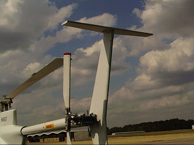
28 Sep 2000 Horizontal stabilizer was modified by cutting off part behind
14.9-15.7 mounting plates #88 and #98. Winglets left out. Flew about ten
traffic patterns in new configuration. Less objectionable side to
side shaking, but balancer still indicates vertical 1.5ips in
climb.
Any flight at appreciable forward speed must be made with left
engine compartment door attached, otherwise the airflow will
damage the carburetor housing (#333). (This was not done on 31
July, and no damage occured at 45 knots. However, longer exposure
and/or higher speed are sure to cause damage.)
Inspected fuel tank and found the cause of the sagging. The
inboard loop clamp (#559) lost its rubber and slid down the frame
member. This allowed the tank to slide aft down and out. The tank
heat shield lodged behind the front EGT probe housing on the
exhaust manifold. The tank was returned to proper position and
secured by a hose clamp on the frame member. The tank heat shield
now maintains a small clearance from the exhaust manifold. It is
possible to install the right engine compartment door, however,
the door makes contact with the side of the tank.
The seat-attachment nuts on the left (2) came off and were found
on the cabin floor. The seat was not at the forward position as
originally set, but, rather, close to the aft position. This must
have been its position on recent flights. The seat was moved full
aft and the nuts were secured.
18 Sep 2000 Put left engine compartment door on and kept right door off (cabin
14.0-14.6 doors both off). Made hover test of oil catcher. Air taxied the
length of taxiway A and back at up to 55 knots. 2/rev levels up to
1.6 ips in transition, then settled to less than 1. Made 1 traffic
pattern at 600' AGL at 50 knots. This was the FIRST TRAFFIC PATTERN
for this aircraft. Saw levels up to 1.25 in climb, then settled to
~0.75. Post flight inspction showed that oil catcher cup separated.
The aluminum strip remained attached but slidd down on right
tension barrel.
20 Sep 2000 Oil cattcher repair: Clamps on both sides of the AL strip
14.6 tightened. Middle of strip coated with duct tape with embedded
wire bhind to stabilize cup under vibration.
22 Sep 2000 AUTOROTATION TEST performed today. Autorotated from ~2000' AGL to
14.6-14.9 ~1000' AGL. With collective full down, rotor overspeeds and I run
out of aft cyclic. Both problems cured by raising collective
slightly. No change in rigging needed.
In climb, read 2/rev vibration levels in excess of 2 ips. Can
reduce level by slowing down or by reducing climb rate. I may be
working engine too hard. Without manifold pressure it is hard to
tell. Temperatures well in green.
Post flight inspection found no discrepancies. Oil catcher of 20
Sep remained intact and contained 2cc.
28 Sep 2000 Horizontal stabilizer was modified by cutting off part behind
14.9-15.7 mounting plates #88 and #98. Winglets left out. Flew about ten
traffic patterns in new configuration. Less objectionable side to
side shaking, but balancer still indicates vertical 1.5ips in
climb.