|
|
Degreeing a cam on the 22R-series engine |
|
|
|
||
| Before I explain why you should degree your camshaft, let's review the function of the crankshaft and camshaft in a four stroke, internal combustion engine.
As the name implies, four stroke internal combustion engines go through four distinct strokes for each combustion cycle: intake, compression, power, and exhaust, also known as suck, squish, bang, and blow. This means that for each combustion cycle, the piston moves up and down twice. This corresponds to two complete revolutions of the crankshaft. Interesting fact: because the camshaft rotates at half the speed of the crank, that means that the camshaft only rotates a quarter turn for each of these strokes. From the crankshaft end of things, the operation is very simple: the piston is moving straight up or straight down every 180 degrees of crankshaft rotation. The camshaft, however, has a much more complex series of tasks to perform, as each valve must be opened and closed at precisely the right moment. To accomplish this, the camshaft rotates once for every two crankshaft revolutions, or one complete revolution per four stroke cycle. As the piston is being pulled down, the intake valve is opening, and the intake mixture is being sucked into the cylinder, or pushed into the cylinder in the case of forced induction motors. Once the mixture has been pulled into the cylinder, the intake valve closes, and the piston begins to rise on the compression stroke. As the piston is rising and the mixture in the cylinder is being compressed, a spark event is initiated at some predetermined point. This ignites the fuel mixture, and as it expands it forces the piston downwards on the power stroke. Once the power stroke is complete, the piston rises again, the exhaust valve opens, the combusted gasses are expelled, and the cycle is repeated. Needless to say, all of these events must occur at just the right time, in the correct order, and for the correct duration. The point where an intake valve is first opened, how much it is ultimately opened, when it closes, and how these events relate to the same events taking place on the corresponding exhaust valve are critical, determining factors in an engine's performance. These characteristics are all built in to your camshaft, and you change them by changing cams. The relationship of these valve events to one another cannot be changed in a 22R engine except by changing camshafts. However, the relationship of these events to the movement and position of the pistons/crankshaft CAN be changed. This is referred to as cam timing, and small changes in your cam timing can make noticable, and sometimes even dramatic changes in your performance. To determine your actual cam timing and make these changes in an informed, logical manner, it is necessary to "degree in" your cam. |
||
|
|
||
What is "degreeing in" your cam, and why is it necessary? |
||
| By "degreeing in" a camshaft, we mean determining its *exact* relationship to the crankshaft. While it would be nice if we could trust the timing marks on the crank pulley and oil pump housing for this, the reality is that there are many components that actually determine cam timing, and small variations in any or all of these components can make the actual cam timing several degrees advanced or retarded from the timing as shown on the stock timing marks.
Consider all of the components that figure in cam and crank timing: the crankshaft and camshaft, obviously, but also the timing gears, timing chain, thickness/height of the head, thickness/height of the cam bearing journals, height of the deck, thickness of the headgasket, precision of the marks on the cast oil pump housing, and the integrity of the stock crank pulley (which is actually a two piece affair on all but the early 22R engines). Quite a few factors to trust, and all it takes is milling a few thou' off the head and/or deck to retard stock cam timing by a few degrees. So, to be as precise as possible, it is necessary to degree in your camshaft. |
||
|
|
||
What do you need to do this? |
||
To degree in a camshaft on a 22R series engine, you need the following special parts and tools:
|
||
|
|
||
First things first: let's get set up |
||
| It is much easier to degree a cam when the engine is out of the vehicle...but I'm going to assume that your engine is still in your vehicle. If it's out of the vehicle, pat yourself on the back, because this just became a whole lot easier for you. For everyone else, roll up your sleeves...
To degree in the cam, you will need to have clear access to the crank pulley. I found that I needed to remove both the power steering belt and the alternator belt. I also found that I needed to remove my fan and pulley from the front of the water pump (you want to remove the four 10MM nuts, and extract the fan and fan clutch as one unit, if possible). Some folks may also need to remove the fan shroud. I got lucky and didn't, but you might, depending on the exact year and style of fan shroud you have installed. If you have an aftermarket electric fan and shroud combo, I believe you will also need to remove that as well. You will also need to remove the stock crank pulley bolt. This can be a major PITA if you haven't done it before, but it's actually pretty easy once you master the basic technique of using the starter and a breaker bar braced against the frame. I am going to assume that you have a method for removing this bolt that you are familiar with, as removing this bolt could make up a decent article in its own right. If you are not sure how to remove this bolt, do a search on one of the major Toyota BBS forums for "crank pulley bolt," and you will see many methods that worked for others. So, remove the following:
|
||
|
|
||
Attach the degree wheel |
||
| Once the belts and fan are out of the way, you can attach the degree wheel to the crank pulley.
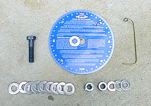
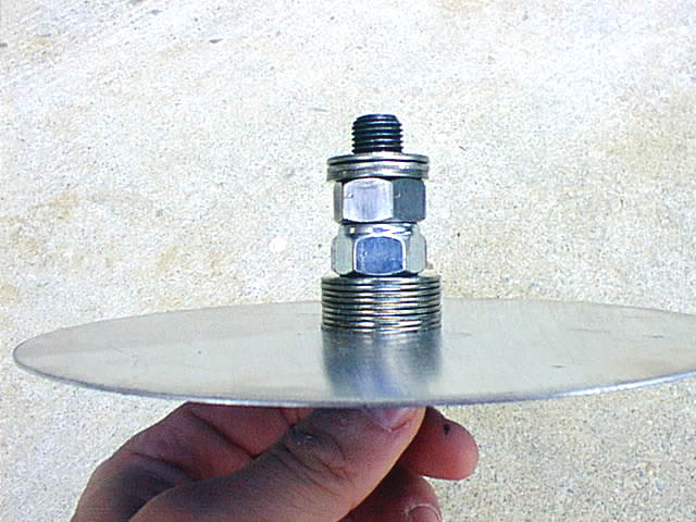
As I said above, I used the Mr. Gasket 7" degree wheel. This wheel comes with a big hole in the center and two aluminum bushings to size this hole down for the more common domestic sized bolts. If you use this wheel, you will need to enlarge the opening of one of these bushings to make it work with the larger Toyota crank pulley bolt. I held the bushing with a pair of Vise Grips and used a 9/16" drill bit to enlarge the hole, which worked fine. To actually attach the degree wheel to the crank shaft, I used a long bolt of the same thread size/pitch as the stock crank bolt, and a number of washers and nuts to allow me sufficient stand-off to keep the degree wheel away from touching the crank pulley. When it was all bolted up, my degree wheel looked like this:
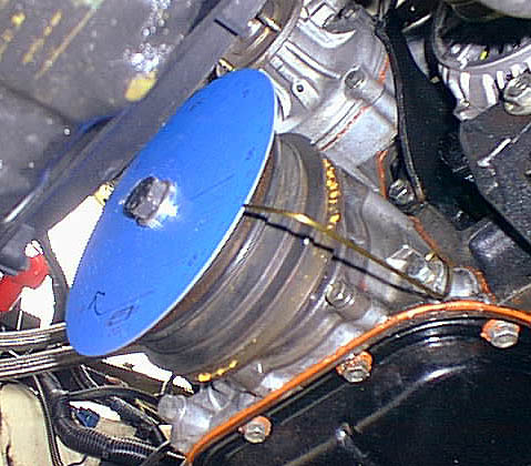
Look at that washer stack! It wasn't pretty, but it worked well...Two things to keep in mind: you will need to be able to move the degree wheel a little bit after you determine positive TDC (explained below), and you will need to use this bolt to turn the engine both forwards and backwards. For these reasons, I used a metric nylon lock nut to keep the washer stack and degree wheel pressed very-firmly-but-not-quite-immobilized against the head of the bolt. You want to have a lot of friction between the two clamping surfaces, but not so much that you can't rotate the wheel a little bit when you need to. I then used a standard nut as a jam nut and spacer against the lock nut, because I was going to be using this bolt to turn the engine and really didn't want anything in the stack to move once I had the degree wheel in position. Finally, I used several very stout washers between the jam nut and the end of the crank shaft. Even though I was doing this operation with the crank pulley still in place, I didn't want these final washers to touch anything other than the surface of the crank, because washers that would be wide enough to span the crank pulley opening might deform when this bolt was tightened, or even worse, then the engine was turned, which would move my TDC marker and force me to start over. So I went with stout washers of a diameter small enough to allow me to tighten this bolt firmly against the crankshaft. After assembling the degree wheel, bolt it firmly to the front of the crank shaft! You will be using this bolt to rotate the engine in both directions, so this bolt needs to be on there tightly, or you might inadvertently break it free when you are moving the engine in reverse rotation. If that happens, you will need to begin this procedure all over again, so make sure that this bolt is on there tight. Finally, after you have the degree wheel in place, attach the heavy wire pointer to any convenient bolt on the timing chain cover or water pump. I chose the lower right timing cover bolt, because this was a convenient spot from which to read the degree wheel. Your finished degree wheel and pointer assembly should look something like this:
|
||
|
|
||
Locate positive top dead center (TDC) |
||
| As mentioned above, you just can't trust the stock timing marks for this operation. Consequently, it is necessary to determine positive TDC before you begin. By positive TDC, I mean the point where the piston is at TDC after you have taken up all of the slack in the timing chain and the engine's other rotating parts.
The overview of this procedure is to install the degree wheel and bring the engine to TDC on the stock marks, and rotate the degree wheel so that it, too, indicates TDC on the wire pointer, as explained below. Next, the engine is backed off 30-40 degrees, and a piston stop is inserted into the cylinder. The engine is then rotated forward until the piston hits the stop, and the position of the degree wheel is noted. The engine is then rotated in the opposite direction until the piston again contacts the piston stop, and the position of the degree wheel is again noted. Positive TDC will be at the middle point of these two readings, and the degree wheel is moved so that it indicates true TDC. For example, if the piston initially contacts the piston stop at 16º BTDC, and then after being rotated in the reverse direction contacts the piston stop again at 20º ATDC, 16 + 20 = 36. Divide 36 ÷ 2 to get the average, 18. Subtract the average from the greater number, and rotate the degree wheel (NOT the engine!) by the difference to bring the degree wheel to true TDC. If the side before TDC was greater, you will rotate the wheel clockwise, and vice versa if the side ATDC was greater. In this example, rotate the wheel 2º counter-clockwise. Repeat the test again to verify that the degree wheel now reads the same each time it hits the piston stop. Here are the step-by-step instructions to determine positive TDC:
|
||
|
|
||
Find the centerline of the intake lobe |
||
| Now that you know the exact location of true TDC, you are ready to find the centerlines of the intake lobe. The intake centerline is used because this is information that is typically included on the cam card that ships with most cams. Note that "intake centerline" is different from "lobe separation angle." If your cam card doesn't have the intake centerline listed, call your cam manufacturer!
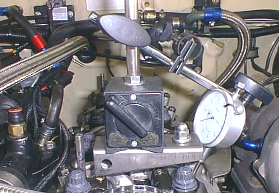
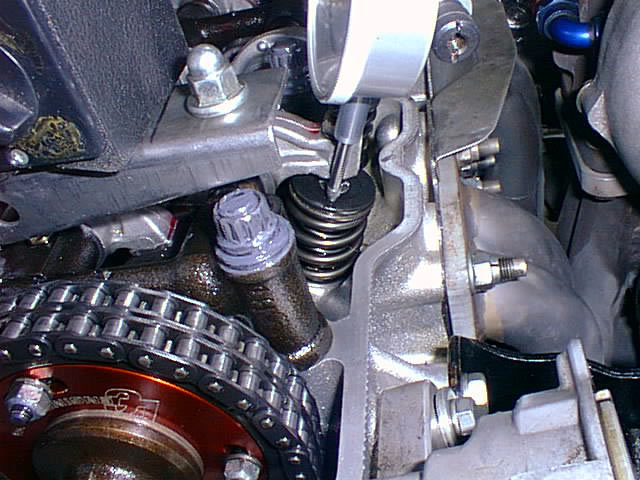
Our goal is to find the highest point on each cam lobe, and map that position to a point on the crankshaft degree wheel. With the engine still set to TDC on the degree wheel, set the valve lash to 0.000". For measuring purposes, valve last just increases cam retard, so it's important to make sure things are set to zero before we go any further. Next, get your dial indicator, and mount it to a sturdy location where you will be able to track the movement of the valve spring retainer, such that the dial indicator's tip will move parallel to the valve spring. Most dial indicators have a magnetic base. Because the head and intake manifolds are aluminum, this can make it hard to mount the dial indicator in a position where it will do you any good. I found that by sandwiching a small piece of flat stock between two nuts on one of the valve cover retainer studs, I was able to work on both intake and exhaust valves pretty easily. My mount looked like this (shown on the exhaust valve, because it made for an easier picture): |
||
|
|
||
What to do with this info? |
||
| Advancing or retarding a cam moves peak torque lower or higher in the rpm range, respectively. If you add torque to the bottom of the rpm range, you take torque off the top, and vice versa. Because the cam is only one engine component, and all engine components need to work together, some engines can benefit from more advance or more retard.
In the case of turbo engines, which typically breathe better at higher rpms, you will usually see more peak power by retarding the cam timing several degrees. However, this increase in peak power will come at the expense of some low end torque. If your turbo is already feeling pretty laggy and you want more torque down low, you may want to forsake more top end power and advance the cam several degrees, which will definitely translate into more seat of the pants/off the line acceleration. 22R/RE engines typically benefit from 2º-3º of cam advance. Finally, keep in mind that 6º is about as much as you would want to move the cam in either direction without making absolutely certain that you have sufficient piston-to-valve clearance. Because the 22RTE pistons have a dish to them, you have a fair amount of clearance, but advancing the cam increases the likelihood of contacting the intake valve, while retarding the cam increases the likelihood of contacting the exhaust valve. Go slow and use your head -- nothing would be worse than bending a valve trying to squeeze another 5 hp from your motor. |
||
|
|
||
Bibliography |
||
| I used the following reference material to help write this article:
CompCams' excellent catalog, especially page 23, "Degreeing in a Camshaft" Crane Cams' "Degreeing in a Cam" The article "Cam Truth", by Buddy Rawls Email and conversations with several individuals, including GaryM. and Tim Jenkins. |
||
Return to Table of Contents |
||
